POST MOUNT 1) Turn off power. 2) Connect fixture ground wire to ...
2) Disassemble the post cup assembly from the fixture. Assembly is held in place by (4) screws at bottom of fixture and (4) hexnuts and lockwashers inside cage.
POST MOUNT 1) Turn off power. 2) Connect fixture ground wire to ground wire from post with wire connector (not provided). Never connect ground wire to black or white power supply wire. 3) Make wire connections (connectors not provided). Reference chart below for correct connections and wire accordingly. Connect Black or Red Supply Wire to:
Connect White Supply Wire to:
MONTAJE EN POSTE 1) Apague la alimentación eléctrica. 2) Conecte el cable de tierra del artefacto al cable de tierra del poste con el conector de alambre (no se provee). Nunca conecte el cable negro o blanco al cable de alimentación eléctrica. 3) Haga les conexiones de los alambres (no se proveen los connectores.) La tabla de referencia de abajo indica las conexiones correctas y los alambres correspondientes.
Black
White
*Parallel cord (round & smooth)
*Parallel cord (square & ridged)
Clear, Brown, Gold or Black without tracer
Clear, Brown, Gold or Black with tracer
Connect Black or Red Supply Wire to:
Insulated wire (other than green) with copper conductor
Insulated wire (other than green) with silver conductor
Black
White
*Parallel cord (round & smooth)
*Parallel cord (square & ridged)
*Note: When parallel wires (SPT I & SPT II) are used. The neutral wire is square shaped or ridged and the other wire will be round in shape or smooth (see illus.)
Neutral Wire
4) Slip post cup at bottom of fixture over post making sure all wires are tucked inside of post. 5) Secure fixture in place using screws. 6) Remove ball knobs at top of fixture and remove roof. 7) Install recommended lamp. 8) Reassemble roof to fixture.
PIER MOUNT 1) Remove ball knobs at top of fixture and remove roof. 2) Disassemble the post cup assembly from the fixture. Assembly is held in place by (4) screws at bottom of fixture and (4) hexnuts and lockwashers inside cage. 3) Using post cup assembly as a template mark position of mounting holes. Mounting holes are the holes that screws were removed from in step 2. 4) Prepare mounting surface for appropriate hardware (not provided) at locations marked in step 3. 5) Turn off power. 6) Connect fixture ground wire to ground wire from source with wire connector (not provided). Never connect ground wire to black or white power supply wire. 7) Make wire connections (connectors not provided). Reference chart below for correct connections and wire accordingly. Connect Black or Red Supply Wire to:
Connect White Supply Wire to:
Black
White
*Parallel cord (round & smooth)
*Parallel cord (square & ridged)
Clear, Brown, Gold or Black without tracer
Clear, Brown, Gold or Black with tracer
Insulated wire (other than green) with copper conductor
Insulated wire (other than green) with silver conductor
*Note: When parallel wires (SPT I & SPT II) are used. The neutral wire is square shaped or ridged and the other wire will be round in shape or smooth (see illus.)
8) 9) 10) 11)
Attach fixture to mounting surface. Install recommended lamp. Reassemble roof to fixture. Mounting surface should be clean, dry, flat and 1/4" larger then the bottom of the fixture on all sides. Any gaps between the mounting surface and the fixture exceeding 3/16" should be corrected as required. 12) With silicone caulking compound, caulk completely around where bottom of fixture meets mounting surface to prevent water from seeping into wiring compartment.
Date Issued: 2/14/03
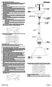
BALL KNOB PERILLA REDONDA
Connect White Supply Wire to:
Clear, Brown, Gold or Black without tracer
Clear, Brown, Gold or Black with tracer
Insulated wire (other than green) with copper conductor
Insulated wire (other than green) with silver conductor
*Note: When parallel wires (SPT I & SPT II) are used. The neutral wire is square shaped or ridged and the other wire will be round in shape or smooth (see illus.)
POST CUP ASSEMBLY CONJUNTO DE LA COPA DEL POSTE
Neutral Wire
SCREW TORNILLO
4) Resbale la taza del poste en el fondo del artefacto sobre el poste, asegurándose de que todos los cables estén metidos dentro del poste. 5) Sujete el artefacto en el lugar utilizando los tornillos. 6) Quite todas las perillas redondas en el tope del artefacto y quite la cubierta superior. 7) Instale la bombilla recomendada. 8) Vuelva a montar el techo del artefacto.
MONTAJE EN PILAR 1) Quite todas las perillas redondas en el tope del artefacto y quite la cubierta superior. 2) Desmonte del artefacto el con junto de la copa del poste. El conjunto se mantiene en el lugar por (4) tornillos en el fondo del artefacto y (4) tuercas hexagonales y arandelas de seguridad dentro de la jaula. 3) Utilizando el conjunto de la copa del poste como un patrón mar que la posición de los agujeros de montaje. Los agujeros de montaje son los agujeros de donde se quitaron los tornillos en el paso 2. 4) Prepare la superficie de monta je para el herraje apropiado (no se provee) en los lugares marcados en el paso 3. 5) Apague la alimentación eléctrica. 6) Conecte el cable de tierra del artefacto al cable de tierra de la fuente con el conector de alambre (no se provee). Nunca conecte el cable de tierra al cable negro o blanco de alimentación eléctrica. 7) Haga les conexiones de los alambres (no se proveen los connectores.) La tabla de referencia de abajo indica las conexiones correctas y los alambres correspondientes. Connect Black or Red Supply Wire to:
Neutral Wire
ROOF TECHO
POST CUP TAZA DEL POSTE
POST POSTE
BALL KNOB PERILLA REDONDA ROOF TECHO
Connect White Supply Wire to:
Black
White
*Parallel cord (round & smooth)
*Parallel cord (square & ridged)
Clear, Brown, Gold or Black without tracer
Clear, Brown, Gold or Black with tracer
Insulated wire (other than green) with copper conductor
Insulated wire (other than green) with silver conductor
*Note: When parallel wires (SPT I & SPT II) are used. The neutral wire is square shaped or ridged and the other wire will be round in shape or smooth (see illus.)
Neutral Wire
8) Acople el artefacto a la superficie de montaje. 9) Instale la bombilla recomendada. 10) Vuelva a montar el techo al artefacto. 11) La superficie de montaje debe estar limpia y seca, ser plana y 1/4" mayor que la parte inferior del artefacto en todos los costados. Cualquier espacio entre la superficie de montaje y el artefacto que exceda de 3/16" se debe corregir según se requiera. 12) Con el compuesto de calafatear de silicona, calafatee todo donde el fondo del artefacto toque la superficie de montaje para impedir la infiltración de agua en el compartimiento del cableado.
Clear, Brown, Gold or Black with tracer. Insulated wire (other than green) with copper conductor. Insulated wire (other than green) with silver conductor. *Note: When parallel wires (SPT I & SPT II) are used. The neutral wire is square shaped or ridg
outlet box ground wire with wire connector, (not provided) after following the above steps. Never connect ground wire to black or white power supply wires. 5) Make wire connections (connectors not provided.) Reference chart below for correct connecti
where back of canopy meets the wall surface to prevent water from seeping into outlet box. Date Issued 10/23/98. IS-9719-US. 4) Sujete la plancha para montar ...
agujero. B) En las lámparas con una arandela acopada. Fijar el alambre a tierra de la caja tomacorriente debajo de la arandela acoada y tornillo verde, y pasar por el .... dela de seguridad y la tuerca hexagonal. 3) Desconecte la corriente. HEXNUT. T
al valor marcado en el lateral del bloque de terminales. Nota: El juego de tornillo de sujeción del interruptor se suministra con los centros de carga convertibles.
that control the power to the fixture or room that you are working on. c) Place the wall ... A) On fixtures where mounting strap is provided with a hole and two.
the above steps. Never connect ground wire to black or white power supply wires. 6) Make wire connections (connectors not provided). Reference chart below for correct connections and wire accordingly. 7) Screw threaded studs into eyelets on backpan.
shutting off the electricity until the work is done. a) Go to the main fuse, or circuit breaker, box in your home. Place the main power switch in the “OFF” position.
ANILLO DEL CASQUILLO. B) En las lámparas con una arandela acopada. Fijar el alambre a tierra de la caja tomacorriente del ajo de la arandela acoada y ...
1) TURN OFF POWER. IMPORTANT: Before you start, NEVER attempt any work without shutting off the electricity until the work is done. a) Go to the main fuse, or circuit breaker, box in your home. Place the main power switch in the “OFF” position. b) Un
A) En las lámparas que tienen el fleje, de montaje con un agujero ... Negro. Blanco. *Cordon paralelo (redondo y liso) *Cordon paralelo (cuadrado y estriado).
1) Turn off power. 2) Attach backpan to outlet box. (Screws not provided). 3) Grounding instructions: (See Illus. A or B). A) On fixtures where mounting strap is .... forma redonda o lisa. (Vea la ilustracíón). Hilo Neutral. GLASS SHADE. DIFUSOR DE.
7 may. 2013 - Coloque la guarnición superior en la parte superior del techo del artefacto. 9) Enrosque el tubo roscado en el remate en el acoplamiento.
Never connect ground wire to black or white power supply wires. ... 12) With silicone caulking compound, caulk completely around where back of canopy meets ...
Turn off power ahead of this loadcenter before installing this kit. 2. Position retaining bracket over and against left side of breaker and drop into place as shown.
Terminal” label in enclosure adjacent to ground bar. Note: Bar wire holes are ... or death. Turn off main power before opening panel. Tension dangereuse.
Connect mounting strap to outlet box. 7) Unscrew the threaded ring from screw collar loop. Take canopy and pass over screw collar loop. Approximately one half ...
del breaker en posición de apagado “off”, que controla (n) la corriente hacia el artefacto o habitación donde está trabajando. c) Coloque el interruptor de pared ...
10) place glass inside cage. 11) raise cage with glass up to fixture. pass holes in edge of cage over threaded studs on fixture. 12) Thread ball knobs onto ...
Your product must be disposed of properly according to local laws and regulations. Because this ... operating conditions for satisfying RF exposure compliance.