FloorSource™ CRFB™ Series Round Floor Box Boîte de ... - Legrand
IMPORTANT: Please read all instructions ... IMPORTANT : Veuillez lire l'ensemble des ... locaux en vigueur et doivent être mis à la terre conformément à ces ...
Legrand/Wiremold electrical systems conform to and should be properly grounded in compliance with requirements of the current National Electrical Code or codes administered by local authorities. All electrical products may present a possible shock or fire hazard if improperly installed or used. Legrand/Wiremold electrical products may bear the mark of a Nationally Recognized Testing Laboratory (NRTL) and should be installed in conformance with current local and/or the National Electrical Code.
CRFB Series Floor Box INSTALLATION INSTRUCTIONS Installation Instruction No.: 1 009 621 – September 2010
IMPORTANT: Please read all instructions before beginning.
PRODUCTS COVERED: CRFB4, CRFBBTC, CRFBCTC, CRFB-X-1, CRFB-X-2, CRFB-X-3 AND CRFB-X-4. Also 8ATC and 8CT Covers when installed on CRFB Series Floor Boxes.
1. Prior to installation, an 8-3/8 ± 1/8 in. [213 ± 3 mm] diameter hole must be cut or preformed into the raised floor panel or wood floor. If knockouts on sides of box are to be used, proceed to steps 4 and 5. Pull cable and conduit through opening prior to termination. 8 3/8" ± 1/8" [213 ± 3mm]
2. If necessary, use bushing(s) and wire tunnel to facilitate wire and cable routing. Remove the temporary cover and the (5) #8 hex screws securing the device mounting plate and lift it out of the box, exposing the internal barriers. Remove necessary knockouts and twistouts between compartments to allow desired wiring layout. Replace the internal barriers and reinstall the device mounting plate back in its original orientation. Temporary Cover Device Mounting Plate
3. Attach flexible conduit and fittings to the steel box body. Terminate wiring devices in compliance with the NEC and local codes. Cover each compartment with the Device Plate that matches both the Location and Type of Device used. Device Location #1 Device Location #4 Device Location #3 Device Location #2
4. Flip locking anchor up and lower box into opening.
5. Tighten mounting screw until steel anchor is adjusted securely below floor.
Steel Anchor
6. Install the floor covering prior to attaching the cover. For carpet installations, the temporary cover plate can be used as a template.
7. Attach cover to box. Remove the appropriate shelf pad tab, exposing the threaded attachment hole. Secure cover to box with screws provided.
Cut Carpet along Temporary Cover Edge Cover Mounting Shelf Pad
9" [229mm]
Remove this Tab Section to attach 8CT Cover Remove this Tab Section to attach CRFB Cover
8. CRFBBTC and CRFBCTC COVERS: Open the lid and insert Cover Attachment Screws through Sealing Washers and attach Cover Flange to CRFB4 Box. Attachment Screw
Mounting Hole
Sealing Washer
Remove this Tab Section to mount CRFB Covers
CAUTION: CRFB4 Floor Box has two sets of Cover Attachment Holes. Use the attachment holes furthest away from the mounting screw.
9. 8CT and 8CTC COVERS: Open the lid and insert Cover Attachment Screws through Sealing Washers and attach Cover Flange to CRFB4 Box. Attachment Screw
Mounting Hole
Sealing Washer
Remove this Tab Section to mount 8CT & 8CTC Covers
CAUTION: CRFB4 Floor Box has two sets of Cover Attachment Holes. Use the attachment holes closest to the mounting screw.
10. FOR 8CT FLUSH STYLE COVERS INSTALLED IN WOOD FLOORS: Create a pocket 9-3/8" diameter [283mm] x 7/32" [5.6mm] deep, concentric with mounting hole from step 1. Place gasket (supplied with cover) in counterbore and attach cover. Apply sealant between edge of hole and flange. Apply Sealant or Grout
9 3/8" [238mm] Counterbore
7/32" [5.6mm] Deep Gasket
11. For factory wired CRFB4 access floor boxes, use Installation Instructions supplied with Walkerflex® Modular Wiring Systems.
CAUTION: Do not make or break connections while circuits are energized.
CRFB Cutting Template
2 15/16" [74mm]
2 25/32" [71mm]
Ø 7 5/32" [182mm]
CAUTION: When printing copies of this template, please be sure template is scaled correctly and is the correct size once it is printed.
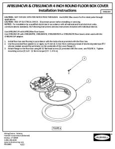
CAUTION: NOT FOR USE WITH FIRE RATED POKE-THROUGHS. Use S1R4CVRxx covers for fire rated poke-through applications. CAUTION: RISK OF ELECTRICAL SHOCK. Disconnect power before installing or servicing. NOTICE: For installation by a qualified electrician
AVISO: La instalación debe ser realizada únicamente por un electricista u otra per- sona calificada de acuerdo con el Código Eléctrico Nacional, el Código ...
applications. CAUTION: RISK OF ELECTRICAL SHOCK. Disconnect power before installing or servicing. NOTICE: For installation by a qualified electrician in accordance with all national and local electrical codes, communications standards, the following
Legrand electrical products may bear the mark of a Nationally ..... 12Formed wire retainers are mounted to the inside of the box to help route card and cables ...
Legrand electrical products may bear the mark of a Nationally ..... 9Formed wire retainers are mounted to the inside of the box to help route wires and cables ...
outlet Boxes and Fittings Classified for Fire resistance Wiremold / legrand (r8209) ... and EFB610BTC service fitting covers in 2 hour fire rated D900 series ...
DAMAGES. Some states do not allow limitations on how long implied warranties last and do not allow exclusion or limitation of incidental or consequential ...
2. Cut line voltage wires, leaving a minimum length of 9" above the opening of the box. 3. Low and line voltage cannot be installed in the same cavity per the.
8 sept. 2010 - Remove four #8-32 pan head screws [1] from top corners of floor box assembly and retain. Remove transition [2] and mounting plate. [3] assemblies from box and retain. Install leveling screws [4] as shown in. FIGURE A. Make conduit conn
Estructura en lámina de acero calibre No. 22, acabado en esmalte horneado. Recipiente interior en lámina de acero calibre. 22, acabado en esmalte horneado.
electrical type RTV silicon sealant compound fully around the perimeter on ... Utiliser le joint de plancher (w) fourni OU appliquer un cordon continu de 6,3 mm ...
... y excluye expresamente daños incidentales o consecuenciales inherentes a su uso. HUBBELL DE MÉXlCO S.A. DE C.V.. Av. Insurgentes Sur # 1228 Piso 8.
Wiring channel areas given in Table 1. (Wiring channel must be removed for feed through applications.) 10. Pull and dress wires. 11. Reinstall wiring channel.
Estructura en lámina de acero calibre No. 22, acabado en esmalte horneado. Recipiente interior en lámina de acero calibre. 22, acabado en esmalte horneado.
Se le di cultaba controlar su ira y tenía poco respeto por la autoridad. Sin embargo, todo esto comenzó a cambiar cuando asistió a la. Granja Milagros (Miracle ...