Installation and Maintenance Instructions Dual Gas Steam Generator & Convection Steamer 24CGA10.2
24CGA6.2
Series: Gemini Model Nos. 24CGA6.2, 24CGA10.2 1333 East 179th Street Cleveland, Ohio 44110 Phone: (216) 481-4900 Fax: (216) 481 3782
Part No. GEMINI-INM B 7/02
FOR THE INSTALLER FOR YOUR SAFETY Do not store or use gasoline or other flammable vapors or liquids in the vicinity of this or any other appliance. WARNING
WARNING Improper installation, adjustment, alterations, service or maintenance can cause property damage, injury or death. Read the installation, operating and maintenance instructions thoroughly before installing or servicing this equipment.
Disconnect power before servicing
IMPORTANT IT IS IMPORTANT TO POST INSTRUCTIONS WHICH ARE TO BE FOLLOWED IN THE EVENT THE USER SMELLS GAS. THESE INSTRUCTIONS SHOULD BE LOCATED IN A PROMINENT LOCATION, AND BE FULLY UNDERSTOOD BY ALL USERS OF THIS EQUIPMENT. THIS INFORMATION SHOULD BE OBTAINED FROM YOUR LOCAL GAS SUPPLIER. ALL SERVICE MUST BE PERFORMED BY A QUALIFIED CLEVELAND RANGE AUTHORIZED TECHNICIAN. The wiring diagram is located on the back of the lower front panel.
RETAIN THIS MANUAL FOR YOUR REFERENCE
INSTALLATION AND MAINTENANCE Gemini Dual Gas Steam Generator and Convection Steamer Table of Contents Chapter CHAPTER 1 PRODUCT IDENTIFICATION ________________________________________ A. MODEL NUMBER ________________________________________________________ B. SERIAL NUMBER ________________________________________________________ C. PRODUCT INFORMATION PLATE __________________________________________ D. 24CGA6.2 PRODUCT VIEW _______________________________________________ E. 24CGA10.2 PRODUCT VIEW _______________________________________________ CHAPTER 2 INSTALLATION INSTRUCTIONS _____________________________________ A. GENERAL ______________________________________________________________ B. INSTALLATION OF THE STEAMER _________________________________________ 1. Locating the Steamer __________________________________________________ a. Location and Clearance Requirements of the Steamer _____________________ b. Exhaust Hood Requirements _________________________________________ c. Positioning and Leveling the Steamer __________________________________ 2. Install Slide Racks _____________________________________________________ 3. Install the Free Air Vented Drain Lines _____________________________________ 4. Install Gas Supply Lines ________________________________________________ a. Gas Supply Requirements ___________________________________________ b. Install Gas Supply Lines ____________________________________________ c. Testing Gas Supply Lines ___________________________________________ 5. Install Electric Power Lines _____________________________________________ 6. Water Supply Requirements and Installation ________________________________ a. Water Supply Requirements _________________________________________ b. Setting the Descale Required Light ____________________________________ c. Install Water Supply Lines ___________________________________________ d. Testing Water Supply Lines __________________________________________ C. STARTUP AND CHECKOUT _______________________________________________ 1. Installation Checkout __________________________________________________ 2. Burner Ignition Test (Lighting and Shutdown Instructions) ______________________ a. Lighting Instructions ________________________________________________ b. Shutdown Instructions ______________________________________________ 3. Start Up Test Procedure Gas Gemini ______________________________________ a. Startup Procedure __________________________________________________ b. Blowdown Inspection _______________________________________________ c. Operating Tests and Final Checkout Procedure __________________________ CHAPTER 3 PREVENTATIVE MAINTENANCE AND TROUBLESHOOTING ____________ A. MAINTENANCE _________________________________________________________ 1. Maintenance Records __________________________________________________ 2. Yearly Maintenance ___________________________________________________ B. TROUBLESHOOTING GUIDE ______________________________________________
Page 1 1 1 1 2 3 4 4 4 5 5 8 8 8 9 10 10 10 11 11 12 12 13 15 16 16 17 18 18 19 19 20 20 21 23 23 23 24 24
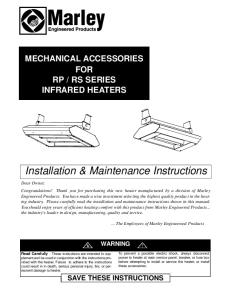
CHAPTER 1 PRODUCT IDENTIFICATION Cleveland Range, Inc. assigns two product identification numbers to each steamer: a model number and a serial number. The model number identifies the product characteristics. The serial number identifies the individual unit. A. MODEL NUMBER This manual covers the Gemini Model No. 24CGA6.2 and 24CGA10.2 Dual Steam Generator and Convection Steamer. Each character of this model number identifies a characteristic of the steamer. The Gemini Model No. 24CGA10.2 is 24 inches wide, a Convection steamer, Gas powered, and an Atmospheric steam generator with a capacity for 10 cooking pans, this model has the extra suffix “.2” to differentiate it from our standard 10 pan model that does not have two separate generators. This manual covers all standard features and options available on Gemini gas steamers. Other than selection of options, there are presently no significant design, parts, or operating differences among steamers with this model number. Figures 1-2 and 1-3 illustrate the two Gemini designs of gas fired steamers and identifies their major components. B. SERIAL NUMBER During manufacture, Gemini Steamers are assigned individual serial numbers. Whenever any inquiry is made with Cleveland Range regarding a steamer the serial number should be referenced. C. PRODUCT INFORMATION PLATE The Product Information Plate on the left side of the unit lists the model and serial number of the steamer. Refer to Figures 1-2 and 1-3 for the location of the plate. Figure 1-1 illustrates a typical Gemini Product Information Plate. The rating plate also lists power and wiring requirements.
Figure 1-1 Gemini Product Information Plates
1
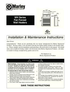
D. 24CGA6.2 PRODUCT VIEW FLUE OUTLET
WATER LEVEL PROBE HOUSINGS LEFT- LOWER COMPARTMENT RIGHT- UPPER COMPARTMENT
DESCALING PORTS
AIR VENTS
RIGHT SIDE SERVICE PANEL
CONTROL PANEL (UPPER)
PRODUCT INFO. PLATE ON LEFT ACCESS PANEL
CONTROL PANEL (LOWER) POWER ON/OFF CONTROLS
RIGHT SIDE SERVICE PANEL
DRIP TRAY
WIRING DIAGRAMS ARE LOCATED ON THE BACK OF FRONT ACCESS PANEL
NOTE: NOT ALL DETAILS ARE SHOWN FRONT ACCESS PANEL
MAIN CONTROL DRAWER
Figure 1-2. Gemini 6-Pan Dual Atmospheric Steam Generator and Convection Steamer 2
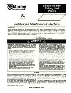
E. 24CGA10.2 PRODUCT VIEW FLUE OUTLET
WATER LEVEL PROBE HOUSINGS LEFT- LOWER COMPARTMENT RIGHT- UPPER COMPARTMENT
DESCALING PORTS
AIR VENTS
RIGHT SIDE SERVICE PANEL POWER ON/OFF CONTROLS (UPPER)
CONTROL PANEL (UPPER)
DESCALE INDICATOR SWITCH PANEL
PRODUCT INFO PLATE ON LEFT ACCESS PANEL
RIGHT SIDE SERVICE PANEL
DRIP TRAY
CONTROL PANEL (LOWER)
POWER ON/OFF CONTROL (LOWER)
NOTE: NOT ALL DETAILS ARE SHOWN
WIRING DIAGRAMS ARE LOCATED ON THE BACK OF FRONT ACCESS PANEL
MAIN CONTROL DRAWER FRONT ACCESS PANEL
Figure 1-3. Gemini 10-Pan Dual Atmospheric Steam Generator and Convection Steamer 3
CHAPTER 2 INSTALLATION INSTRUCTIONS A. GENERAL This equipment should only be installed by qualified, professional plumbers, pipe fitters, and electricians. ·
The installation of this steamer must conform with the Basic Plumbing Code of the Building Officials and Code Administrators International, Inc. (BOCA), the National Fuel Gas Code, ANSI Z223.1-(latest edition) or the Natural Gas Installation Code CAN/CGA-B149.1 or the Propane Installation Code CAN/CGA-B149.2 as applicable, The National Electrical Code, ANSI/NFPA No. 70-(latest edition) or the Canadian Electrical Code, CSA C22.2 as applicable, the Food Service Sanitation Manual of the Food and Drug Administration (FDA) and all applicable state and local codes and regulations.
·
The installation instructions must be read in their entirety before starting the installation of this steamer.
WARNING DEATH, INJURY, AND EQUIPMENT DAMAGE could result from the improper installation, adjustment, alteration, service or maintenance of a steamer or installation of a unit damaged during shipment or storage. Any of these conditions could also void the equipment warranty. DO NOT INSTALL a Gemini steamer that has been damaged. Install the Gemini steamer according to the policies and procedures outlined in this manual. ·
To install this steamer, the following requirements must be considered when selecting a location. a. A suitable drain must be available within 12 ft. of the steamer. b. An electrical supply matching the power requirements found on the rating plate must be available. c.
A gas supply matching the fuel requirements found on the rating plate must be available.
d. The location must have sufficient space to meet the clearance requirements of the steamer as outlined in Chapter 2, Section B, Part 1, “Locating the Steamer”. e. A water supply meeting the requirements outlined in Chapter 2, Section B, Part 6 “Water Supply Requirements and Installation” must be available. B. INSTALLATION OF THE STEAMER After selecting the steamer’s operating location the steamer can be positioned, and installed. After Final Setup and Checkout, the Gemini steamer should provide years of reliable operation.
4
CAUTION Malfunctions and equipment damage may result from improper mounting. Malfunctions and/or damage resulting from improper mounting are not covered by the equipment warranty. The steamer MUST BE LEVEL BOTH FRONT TO BACK AND SIDE TO SIDE in all mounting arrangements. Catastrophic damage will result from shifting the steamer more than o 10 out of level with power supplied to the unit. 1. Locating the Steamer a. Location and Clearance Requirements of the Steamer For safe and efficient operation, observe the following criteria when selecting an operating location for the Gemini steamer. 1) The unit should be installed in an area that is free and clear of combustible materials. 2) Do not locate the steamer directly over a floor drain. 3) A proper air supply for combustion and ventilation is critical to safe, efficient operation of Gemini gas steamers. 4) Do not install any heat producing equipment near the air vents of the equipment. Do not block the air vents of the unit. Do not store articles on top of the unit.
WARNING All clearance requirements above, below, and around the unit are the same for non-combustible locations as for combustible locations.
.
5) Figure 2-1 and 2-2 illustrate the dimensions and clearances required for these steamers. Maintain the following minimum dimensions around the unit for safe and efficient operation, maintenance and service. · · ·
Maintain a 3-inch operating clearance at the sides of the unit, and at least a 3-inch clearance at the back. A 12 in clearance is recommended on the right side for servicing the steamer. Approximately 24 inches of clearance is recommended in front of the unit for opening the door and standard pan clearance.
6) The steamer must be level both front to back and side to side. Select an operating surface that is level enough to allow leveling the unit without extreme adjustment of the legs. 7) The location selected must be capable of supporting 650 lbs. for a Gemini steamer. This includes the weight of the water and the food.
5
OPERATING CLEARANCE SECONDARY CLEARANCE
GAS 1-1/4" IPS line size, 3/4" connection NATURAL
PROPANE
BTU
Piping 3/4" N.P.T Piping 3/4" N.P.T. Supply pressure
50,000 each Generator
Supply pressure
4.50" W.C. Min. 11.00" W.C. Min. 14.00” W.C. Max. 14.00” W.C. Max.
ELECTRIC
COLD WATER
CLEARANCE
DRAINAGE
120V-1Phase, 60 Hz.
35 PSI minimum
RIGHT = 12.00" for service 1-1/2" dia.
2 Fans & controls
60 psi maximum
SIDES = 3.00”
Do not connect other
150 watts each
(1) 3/8" dia. IPS for Generator (1) 3/8" dia. IPS for
REAR = 3.00”
units to this drain
FRONT = 24.00”
Condenser
Drain must be vented
100,000 total Do not use PVC pipe
Manufacturer must be notified if unit will be used above 2,000 feet
Figure 2-1 Gemini 24CGA6.2 Dimensions and Clearances
6
OPERATING CLEARANCE SECONDARY CLEARANCE
GAS 1-1/4" IPS line size, 3/4" connection NATURAL Piping 3/4" N.P.T
PROPANE Piping 3/4" N.P.T.
Supply pressure
Supply pressure
4.50" W.C. Min. 14.00” W.C. Max.
11.00" W.C. Min. 14.00” W.C. Max.
BTU 72,000 each Generator
ELECTRIC
COLD WATER
CLEARANCE
DRAINAGE
120V-1Phase, 60 Hz.
35 PSI minimum
RIGHT = 12.00" for service 1-1/2" dia.
2 Fans & controls
60 psi maximum
SIDES = 3.00”
Do not connect other
150 watts each
(1) 1/4" dia. IPS for Generator (1) 1/4" dia. IPS for
REAR = 3.00”
units to this drain
FRONT = 24.00”
Condenser
Drain must be vented
144,000 total Do not use PVC pipe
Manufacturer must be notified if unit will be used above 2,000 feet
Figure 2-2 Gemini 24CGA10.2 Dimensions and Clearances
7
b. Exhaust Hood Requirements The Gemini gas steamer MUST be installed under an exhaust hood. The exhaust hood must extend over the gas flue opening on top of the steamer and meet the following requirements: 1). The Gemini gas steamer must be vented in accordance with all local, state and national codes for venting gas fired appliances. 2). The exhaust hood must be sized for the cumulative ventilation requirements of all the gasfired appliances in the area including the Gemini. Figures 2-1 and 2-2 contains the dimensions, gas flow, and BTU per hour data required to calculate the minimum required hood dimensions and minimum ventilation capacity (c.f.m.) for the Gemini 6 and 10 pan steamers. 3). Do not connect the exhaust hood directly to the flue outlet of the steamer. 4). If an existing hood cannot be used, a new one should be constructed over the steamer. c. Positioning and Leveling the Steamer NOTE: If there is not enough room to work on the drain, electrical, gas and water lines with the unit in place, postpone positioning and leveling the unit until all site preparation is completed. After the lines are prepared, position and level the steamer, then connect the utility lines.
WARNING INJURY AND EQUIPMENT DAMAGE could result from improper lifting. A Gemini Steamer weighs approximately 545 pounds. Use enough workers with experience lifting heavy equipment to place the steamer on the supporting surface. Move the steamer into position. Using a level, adjust the adjustable legs until the unit is level. 2. Install Slide Racks a. Refer to Figure 2-3. Each rack has four loops: two at the top and two at the bottom. Hold the slide rack so the ends of the hanger loops are towards the cavity wall, as shown in the figure. b. Slide one rack into the compartment with loops toward one side. c.
Hook the loops over the top and bottom pins.
d. Repeat steps a. through c. for the other racks.
Figure 2- 3 Slide Rack Installation
8
3. Install the Free Air Vented Drain Lines Furnishing and installing the drain line is the responsibility of the owner and/or installer. Figure 2-4 illustrates a drain layout recommended by Cleveland Range.
WARNING DEATH, INJURY, AND EQUIPMENT DAMAGE could result from improper installation of the drain outlet lines. Improper installation of these lines could void the Gemini Steamers warranty. The following restrictions are critical to the safety of personnel and equipment, and must not be violated under any circumstances. o Do not connect the drain line into PVC or any drain material that cannot sustain 180 F. Do not connect drains from any other equipment to the drain line of the Gemini Steamer. Do not connect the drain outlet extension line directly to a floor drain or sewer line. The drain line must be free air vented, have gravity flow from the steamer, and terminate outside the perimeter of the unit. a. The drain lines must be installed in compliance with the Basic Plumbing Code of the Building Officials and Code Administrators International, Inc. (BOCA), and the Food Service Sanitation Manual of the Food and Drug Administration (FDA) and any state, provincial or local codes. b. Do not install the steamer directly over a drain. Steam rising up out of the drain will adversely affect operation, cooling air ventilation and may damage electrical components. c.
The total length of pipe and number of bend fittings required to reach the open drain determines the pipe size used to extend the drain line to an open drain. · ·
If the drain outlet extension requires 6 feet or less of pipe, and no more than two elbows are required, 1- ½ inch pipe and fittings are acceptable. If the drain outlet extension requires 6 to 12 feet of pipe, or requires three or more elbows, 2-inch pipe and fittings are required.
d. The drain line must have a gravity flow from the steamer drain outlet to the floor drain. Do not install a trap in the drain line. e. Free air venting requires a minimum of 1 inch of clearance between the end of the drain line and the top of the floor drain. f.
Do not connect the steamer drain directly to drains or plumbing of any other equipment.
g. Refer to Figure 1-2 or 1-3 depending on Model. Connect the drain to the steamer as described below: · ·
The steamer is supplied with a 1-½ -inch pipe connection at the bottom of the unit (Figure 2-4). When assembling the pipes and fittings of the drain outlet extension, apply a hardening type pipe sealant to the threads, and thread them together FINGER TIGHT ONLY. DO NOT USE A WRENCH.
9
DRAIN
1” CLEARANCE MINIMUM
DRAIN LINE
REAR DRAIN
Figure 2-4 Typical Drain Connection for Both Models (Gemini 6-pan shown)
4. Install Gas Supply Lines a. Gas Supply Requirements 1) Make sure the gas supply type matches the type of gas shown on the rating plate. 2) Make sure that the gas supply pressure does not exceed 14” water column, and falls within the acceptable gas pressure range shown below: ·
Natural gas pressure must be between 4½” – 14” water column.
·
Propane gas pressure must be between 11” – 14” water column.
b. Install Gas Supply lines The installer/owner is responsible for furnishing and installing the gas supply lines, valves, regulators, and accessories. When installing the gas supply lines and accessories, observe the following: 1). The installation must conform with local codes, or in the absence of local codes, with the National Fuel Gas Code, ANSI Z223.1 (latest edition) or the Natural Gas Installation Code, CAN/CGA-B149.1 or the Propane Installation Code, CAN/CGA-B149.2 as applicable. 2). THE GAS SUPPLY PRESSURE TO THE STEAMER MUST NEVER EXCEED 14” WATER COLUMN (½ psi). If the gas supply pressure exceeds 14” water column; a pressure regulator must be installed in the gas supply plumbing to reduce the pressure to the steamer.
MAIN GAS SUPPLY
3). Refer to Figure 2-5 for the recommended layout of the gas supply lines. Refer to Figure 2-1 or 2-2 depending on which model you have, Detail A for the location of the ¾ inch gas inlet of the steamer. 4). Install a manual shut off valve between the gas supply and the steamer. See Figure 2-5. From now on this valve will be referred to as the Main Manual gas valve. 5). It is recommended that a sediment trap (drip leg) be installed in the gas supply line. See Figure 2-5. 6). Use a pipe sealant compound, which is resistant to LP gas.
10
PRESSURE REGULATING VALVE (IF REQUIRED)
Gemini
MAIN MANUAL GAS SHUTOFF VALVE DRIP LEG
GAS MANIFOLD CONNECTION
GAS SUPPLY CONNECTION A ON DIMENSION DIAGRAM
Figure 2-5, Recommended Gas Supply Line Layout
c. Testing Gas Supply Lines
WARNING FIRE OR EXPLOSION HAZARD LEAKING GAS CAN CAUSE FIRE OR EXPLOSION WITH PROPERTY DAMAGE, INJURY OR LOSS OF LIFE. If the installer smells gas, or suspects there is a gas leak, immediately refer to the posted gas leak instructions. The posted instructions are provided by the local gas supplier, and supersede any other instructions. Until the leak is stopped observe the following precautions in addition to the posted instructions: Do not light or start any appliance. Do not touch any electrical switch. Do not use any phone in the building. Immediately call the gas supplier from a phone away from the building. Follow the gas supplier’s instructions. If the gas supplier cannot be reached call the fire department. 1). Leak Testing the appliance Before permanently turning on gas to the steamer or after any service to the gas supply, test all pipe joints for leaks with a soap and water solution. All leaks must be corrected before attempting to operate the steamer. 2). Pressure Testing the Gas Supply Lines The steamer must be isolated from the gas supply system during any pressure testing as follows: ·
The appliance and its main manual shut-off valve must be disconnected from the gas supply piping system during any pressure testing of the system at test pressures in excess of 14” water column (½ psi or 3.45 kPa). Be sure to leak test all fittings with a soap and water solution after reconnecting the gas supply.
·
The appliance must be isolated from the gas supply piping system by closing its main manual shut-off valve during any pressure testing of the gas supply piping system at test pressures equal to or less than 14” water column (½ psi or 3.45 kPa).
5. Install Electric Power Lines The electrical supply must match the power requirements specified on the steamers rating plate and be made in accordance with the following requirements. a. The steamer must be grounded and have the electrical power lines installed in accordance with local codes and/or the National Electric Code, ANSI/NFPA No. 70-LATEST EDITION (USA) or the Canadian Electrical Code, CSA C22.2, as applicable. The wiring diagram is located on the back of the lower front panel. b. Optional Factory Supplied Plug ·
If a cord and plug are supplied with the unit, plug the unit into a grounded outlet dedicated to the steamer.
·
A cord-equipped appliance will be equipped with a three-prong (grounding) plug for your protection against shock hazard, it should be plugged directly into a properly grounded threeprong receptacle. Do not cut off or remove the grounding prong from the plug.
11
c.
A main disconnect switch and a separate fuse or breaker should be installed near the unit as shown in Figure 2-6. See Figure 2-1 or 2-2 for the steamers power requirements. Throughout the remainder of this manual the fused disconnect switch is referred to as the main external power switch.
d. Refer to the connection diagrams in Figure 2-7, and connect the wires to the terminal block and ground connector accordingly. MAIN EXTERNAL POWER SWITCH
Gemini
ELECTRICAL CONDUIT INLET
DRAIN LINE
GROUND LUG
TERMINAL BLOCK
COLD WATER SUPPLY LINES
Figure 2-6, Recommended Electrical Layout
Figure 2-7, Electrical Connections
6. Water Supply Requirements and Installation a. Water Supply Requirements
CAUTION Using water not within the limits specified in this manual could void or reduce Cleveland Range’s warranty coverage of the steamer. 1). Water Quality As with any steam generating equipment, poor water quality degrades the performance of the steamer. Check the quality of supply water as described below before starting construction of the water supply lines. If a water treatment system must be installed to achieve acceptable water quality, install it before connecting the water supply lines to the Gemini Steamer. If softened or chlorinated water is used in a Gemini steam generator, a carbon type filter must be used for the water before it enters the steamer to remove Chlorine or other salts. If the water supply is treated or softened either by the Water Company or on the premises, it may contain chlorine or various salts. These additives are damaging to the steam generator. Salts and chlorine used to soften or treat water cause rapid scale buildup, and/or increased corrosion if allowed to flow into the steamer. Contact a local water treatment specialist for an on-the-premises water analysis. The recommended minimum feed water quality requirements for the steamer are listed in Table 2-1.
12
Table 2-1. Minimum Water Quality Requirements Scale Forming Factors Total Dissolved Solids Silica Alkalinity
less than 60 parts per million less than 13 parts per million less than 20 parts per million
Corrosion-Causing Factors: Free Chlorine Chloride PH factor
less than 0.5 parts per million less than 30 parts per million greater than 7.5
2). Water Supply System Provide a water supply system that fulfills the requirements of the limits listed in Table 2-1. The 2 supply must provide a minimum dynamic pressure of 35 psi (2.4 kg/cm ) and a maximum static 2 pressure of 60 psi (4.1 kg/cm ). ·
If analysis shows that the supply water is NOT within the required limits, either a water treatment system and/or carbon filter must be installed in the line feeding the steam generator or the frequency of maintenance, cleaning, and descaling must be increased beyond that recommended in the maintenance schedule (Chapter 3). If more frequent descaling is selected as the means of protecting the steamer from premature failure, the “DESCALE REQUIRED” light timing should be readjusted to reflect the increased cleaning schedule.
b. Setting the Descale Required Light The Descale Required Light feature tracks the number of hours the unit has been operating since it was last reset, and lights when it is time for descaling.
DESCALE REQUIRED LIGHT/RESET SWITCH. NOTE: ORIENTATION OF SWITCH WILL VARY DEPENDING ON MODEL
1). General The Descale Required Light consists of an indicator light, a solid state timer module, and a reset/rocker switch. (The light and reset switch consist of a single device on the front panel identified by the “DESCALE REQUIRED” label.) See Figure 2-8. The timer is a digital clock module inside the unit that keeps track of how many hours your steamer has been in operation since the last reset of the timer.
Figure 2-8 Descale Required Light and Timer Module
13
2). Determining the Timer Setting
Suggested Timer Settings Based on Water Quality/Hardness
The recommended setting of the Descale Required light is determined by the quality of the water supply. Table 2-2 suggests appropriate timer settings.
Quality of Feed Water Poor Average Good Very Good
3). Switches Determine Timer Setting The Timer Module contains a bank of miniature switches that determine the timer setting. The switches can be placed in either the ON or OFF positions.
Hardness (grains/gal.)✳ 25 15 7 3 or less
Timer Settings 128 hours 256 hours 384 hours 512 hours
✳17.1 ppm = 1 grain/gal of hardness Table 2-2
ON 1 2 3 4
Each switch has a specific value. The total timer setting is the sum of the values of all of the switches that are in the ON position. (See Figure 2-9 for switch values).
128 256 512 1,024
The Descale Required Light timer is preset at the factory with switches 1 and 2 turned ON. Adding the values of these switches results in a setting of 384 hours (128+256=384).
Switch Values (in Hours)
Figure 2-9 Switch Values 4). Procedure to Change Descale Required Light Timer Switch Settings Read this procedure completely before starting. The Descale Required Light Timer setting should be changed only by qualified maintenance technicians familiar with electrical safety procedures.
WARNING Disconnect the electrical power before servicing.
a) Make sure all power to the unit is OFF. b) Determine the time you want to set. c) Locate the timer modules, which are located horizontally in the front, at the right and left of the electrical drawer. d) Set the timer switches. It is a good idea to turn them all OFF first then turn ON the desired switches. e) Verify that the switches are in the desired position. Replace the electrical drawer cover.
14
c. Install Water Supply Lines The installer/owner is responsible for the correct water connection of the unit. When connecting the water supply lines observe the following instructions and all national and local codes and regulations: 1). Never connect the unit to HOT WATER. The condenser system of the steamer will not work properly if it is connected to HOT or WARM water. 2). The water supply should have a minimum flow pressure of 35-psi (2.4 kg/cm²) and a maximum static pressure of 60-psi (4.1 kg/cm²). If the static pressure is above 60 psi, a pressure regulator must be used set at approximately 50 psi. Pressure above 60 psi can damage the solenoid valves. 3). The Gemini Steamers are supplied with two connection points for incoming water, one feeds the condensers and the second supplies feed water to the generators. If the local water supply is of poor quality (see Chapter 2, Section 6, Part a.1 for details of water quality), it is recommended that treated or otherwise filtered or conditioned water be used to supply the feed water to the generators. In the case of using a separate water supply, use the layout shown in Figure 2-11. 4). Pay attention to the following requirements and recommendations when connecting the steamer to the water supply: a) Cleveland Range recommends the plumbing layout illustrated in either Figure 2-10, for installations using a single water supply or Figure 2-11 if a separate conditioned water supply is being used for boiler feed. Note: If using a single water feed to the system the supply piping to the tee fitting should be of at least the next largest size of pipe to the connection provided at the steamer. b) The steamer has two 3/8-inch IPS fittings (Model 24CGA6.2) or two 1/4-inch IPS fittings (Model 24CGA10.2) for the water connections to the generator and to the condenser. These fittings are detailed as D and E in Figure 2-1 or 2-2. c) Install a manual water valve between the main cold water supply line(s) and the steamer supply lines. d) The National Sanitation Foundation (NSF) requires installation of a check-valve in all supply lines in accordance with and as required by local plumbing codes. e) The water supply line(s) should be designed so that the unit can be moved for service.
Gemini Condenser Solenoids
Steam Generator Solenoids
Water Connection D on Dimension Diagram Strainer*
Air/Water Column (if required) Check Valve Main Cold Water Supply
Water Connection E on Dimension Diagram
Pressure Reducer (if required)
Figure 2-10 Cleveland Range Single Water Supply Arrangement (*May be installed internal to the steamer on some models)
15
Main Water Shut Off Valve
Flow
Gemini
Water Connection D on Dimension Diagram
Strainer*
Check Valve
Air/Water Column (if required) Standard Cold Water Supply Flow
Condenser Solenoids
Steam Generator Solenoids
Pressure Reducer (if required)
Water Connection E on Dimension Diagram
Main Water Shut Off Valve Conditioned Cold Flow Water Supply
Figure 2-11 Cleveland Range Single Water Supply Arrangement when Using Separate Conditioned Feed Water Supply (*May be installed internal to the steamer on some models) f)
A 40 or 50-mesh water strainer (dirt filter) of one of the types and construction illustrated in Figure 2-12, Cleveland Range part number 106684 or 19870 is supplied with the unit and should be installed where indicated in the plumbing layout. Note: On some Models the strainer has already been installed as part of the internal water piping. · ·
Make sure the arrow on the strainer body points in the direction of flow into the steamer. Install the strainer so the access nut points down.
P/N 106684
P/N 19870
Figure 2-12 Water Strainer Assembly
g) Construct all supply lines up to the point of installing the strainer. Flush the water supply lines before connecting the strainer. h) Apply pipe dope or Teflon tape to any threaded connection. d. Testing Water Supply Lines 1). Check all connections for proper tightness. Remove the side panel to inspect water connections inside the steamer. 2). Open the water supply valves. 3). Check all lines and connections for leakage, both inside and outside the steamer. 4). If Startup and Checkout will be performed next, leave the right side panel off; otherwise, replace the side panel and secure it to the unit.
C. STARTUP AND CHECKOUT The Startup and Checkout procedure prepares a recently installed or repaired steamer for operation. The procedures check proper electrical, gas, water, and drain connections to the steamer, and verify basic steamer operation.
16
1. Installation Checkout Use the Installation Checklist Table 2-3, to check the overall installation. Table 2-3. Installation Check List TASK
REFERENCE Page No.
Preparation Verify Electric Power Requirements. Verify Gas Supply Requirements Verify Exhaust Hood Requirements Test supply water quality. Check operating location clearances Installation Verify steamer is level. Check drain line connection. Check Exhaust Hood Check electrical line connection. Check water supply connection. Test water supply lines. Check Gas Supply Connection Leak Test Gas Supply Connection Check Burner Ignition Test Perform Startup and checkout.
6 or 7 10 8 12 6 or 7 8 9 8 11 15 16 10 11 18 19
Notes on installation:
17
COMPLETED
2. Burner Ignition Test (Lighting and Shutdown Instructions) It is recommended that this test be performed before beginning the Startup Test Procedure. This will insure that the basic heating system is operating normally before reviewing the overall operation of the steamer, since much of the operation is dependant on the operation of the burner control system.
WARNING DO NOT TRY TO LIGHT THE BURNERS OR PILOT WITH A FLAME. The Gemini has an electronic ignition system, which automatically lights the pilot and burners, senses the flame, and controls gas flow. This provides precise burner control, safety ignition, and shutdown features. DEATH, INJURY OR EQUIPMENT DAMAGE may result from an improperly adjusted gas control and ignition system. Do not alter any adjustments on this electronic control or automatic gas valve. If adjustment is required, contact an authorized service center. Cleveland Range is in no way responsible for the operation or safety of this equipment if the controller, valve or igniter probe is adjusted by anyone other than a Cleveland Range authorized service representative. a. Lighting Instructions This is a functional test of the intermittent pilot ignition system. Pilot/burner ignition is completely automatic. NOTE: Each compartment has its own steam generator and control system, and must be started independently. 1). If not already done during prior installation or testing: · Test the water supply lines. · Leak test the gas supply lines. · Check that the ON/OFF valve of the automatic gas control valve is in the ON position. · Turn the Main Manual gas valve to the open position. 2). The controls should be set as follows: · The main power switch should be in the OFF position. · The steamer’s ON/OFF levers/switches should be set to the OFF position. · The MANUAL/TIMED switches should be set to the TIMED position. 3). Turn ON the electrical power to the steamer at the main power switch. NOTE:
When initial power is supplied to the steamer with the ON/OFF lever/switch in the OFF position, a 3-minute blowdown cycle starts. This blowdown cycle stops when the 3 minutes have elapsed or the ON/OFF lever/switch is changed to the ON position.
4). Turn ON the electrical power to the steamer at the ON/OFF levers/switches. a) The red indicator lights in the control panel light and water begins filling the steam generator. The pilot/burners do not light until water reaches the safety level in the probe assembly.
18
b) After 2 to 3 minutes, water reaches the middle probe (safety level). c) Turn on a cooking compartment (for non-”Instant ON” units only) and the burners will light with a distinctive sound. NOTE: Cooking compartment doors must be closed first. ¨ If the burners light within 5 minutes of turning the unit ON, the ignition controls are functioning normally. End this test procedure here. ¨ If the burners do not light within 7 minutes, there may be air in the gas supply lines proceed to step 5. 5). Turn off electrical power to the Steamer, at both the ON/OFF levers/switches and the main power switch. NOTE:
When the burners fail to ignite, a safety circuit in the igniter control de-energizes the system and closes the automatic gas valve. The safety circuit resets when the steamer’s power is turned OFF and then back ON.
6). Wait 5 minutes and then repeat steps 2 through 6. If this is a brand new installation, or an excessive amount of air in the lines is suspected for any other reason, it may be necessary to bleed the excess air from the lines. This should be done at a union or connection as close as possible to the inlet of the automatic gas valve. 7). If the burner does not light after the third attempt, call a Cleveland Range authorized service representative to adjust the burner controls. 8). Go to Shutdown Instructions. b. Shutdown Instructions 1). Turn off electrical power to the steamer, at both the ON/OFF levers/switches and the main power switch. 2). Turn off gas supply at the main manual gas valve. 3. Start up Test Procedure Gas Gemini Cleveland Range steamers have either a manual dial timer control panel, an electronic control panel with a keypad timer control, an “Instant ON” control system (available only for the Gemini 6 pan model) or an ON/OFF control panel. There are a few operating differences between steamers with the dial timer controls and steamers with the keypad controls. The differences in cooking operation of the two types of timer controls are fully explained in the separate OPERATORS MANUAL. The “Instant ON” model has no operating controls other than the Power ON/OFF lever, and begins heating to produce steam as soon as the ON/OFF lever is set to the ON position. The ON/OFF Control Panel, operates exactly like the manual operation of the timed models except a selector switch is used to turn the steam to the cooking compartments ON and OFF. After performing the startup procedure, perform the test procedure as appropriate to the control panel on the steamer being tested. Ignore any steps, which do not apply to the steamer being tested. This procedure is appropriate for steamers with keypad control panels, dial timer control panels, “Instant ON” or manual control panels. Read through all steps of this procedure before starting. Complete the startup procedure before starting the actual operating tests. This procedure should be performed only by a service technician or installer. NOTE: Each compartment has its own steam generator and control system, and must be started independently.
19
a. Startup Procedure 1. Check that the water supply line valves are open. 2. Check that the main manual gas valve is open. 3. Open the steamer door. Check for proper installation of the drain screen, slide racks, and door gasket assembly. Be sure the drain is not blocked. Shut the steamer door. 4. Refer to electrical layout, Figure 2-6, and Figure 2-1 or 2-2. Be sure the main power switch is in the OFF position. Verify installation of the proper size fuses or circuit breakers. 5. Set the control panels as follows: a) Set the ON/OFF levers/switches to the OFF position. b) Press the TIMED (top) end of the TIMED/MANUAL switch for both compartments. c) The timer setting is not important while the ON/OFF lever/switch is in the OFF position. · The keypad timer display is blank without power. · Even if the timer is not zeroed, the timing circuits are not powered. 6. Remove the right side access covers (see Figure 1-2 or 1-3).
WARNING Death, severe electrical shock or equipment damage can result from touching any component inside unit when main power switch is in the ON position. Use extreme caution during testing with the access cover removed. b. Blowdown Inspection (continue from Startup Procedure) 1. Turn ON electric power to the steamer at the main power switch. The steamer will immediately start a 3-minute blowdown cycle. During blowdown, the fill and drain valves are fully open while the steam generator drains are flushed with fresh water. 2. Stop the blowdown cycle before it is complete by setting the ON/OFF levers/switches to the ON position. This energizes the operating control circuits, the red indicator on the control panels light, blowdown stops, and the steam generator fills with water. 3. Restart the blowdown cycle by setting the ON/OFF switches to the OFF position. During the automatic blowdown cycle, make the following checks. · Check for plumbing leaks. · Look at the one-inch vent gap between the steamer drainpipe and the floor drain. A steady stream of water should be draining from the steamer. · NOTE: The ON/OFF lever must be turned fully to the OFF position to START the proper blowdown sequence. · After about 3 minutes, the cycle is complete. Check the gap at the steam drain; there should be no more water flow at this point. NOTE: If the clean light comes ON, and this is a new installation or the steamer is not in need of descaling reset the clean timer; otherwise arrangements should be made to descale the steamer soon.
20
c. Operating Tests and Final Checkout Procedure (Continue from Blowdown Inspection) (Sequence of Operation)
WARNING When checking inside the steamer always open the door slowly and stand to the side and back away from the steamer. Water leaking from the door gasket can be a sign of a blocked drain. If the drain is blocked, hot water can accumulate inside the compartment and spill out when the door is opened. 1). At the start of this test the controls should be set as follows: · The main power switch is ON. · The ON/OFF levers/switches are OFF (The red indicators on the control panels are not lit). · The TIMED/MANUAL switch is in the TIMED position. (or for ON/OFF models the ON/OFF compartment selector switch is in the OFF position) · The timer display will be blank while the ON/OFF lever/switch is set to OFF. [key pad models] 2). Set both the upper and lower compartment timers to zero. a). KEYPAD MODELS If the timer is not zeroed (00:00) when power is turned on in step 3, press and hold the CLEAR key on the key pad control panel to zero the timer. b). DIAL TIMER MODELS If the Timer is not zeroed, turn the dial counter clockwise until it points to the 0 mark. 3). Set the ON/OFF lever/switch to the ON position. As the steam generator fills with water, check the following functions. a). The red ON/OFF indicator light turns ON. The fill valve opens and water begins to fill the steam generator. The combustion blower turns on to purge the combustion chamber. b). After a few minutes, water appears in the bottom of the probe cylinder. As the water level in the steam generator rises; ¨ Check that no water flows from the drain opening. ¨ Check for plumbing leaks. 4). When the water in the steam generator reaches a safe operating level (which is the level of the middle probe), the combustion blower shuts off and the pilot ignition cycle starts. The steam generator begins to heat the water to stand-by temperature by lighting the pilot/standby burner. a) Water continues to fill the generator and the water level in the probe cylinder continues to rise. b) The water in the probe cylinder stops rising, when water reaches the upper probe. ¨ If the water level continues to rise above the tip of the higher probe, have a qualified service representative check the probe circuit. 5). Set the TIMED/MANUAL switches of both compartments to MANUAL (or for ON/OFF Models set the compartment selector switches to ON), the steaming cycle starts. Check the following functions. ·
If the water level in the steam generator is above the lower probe, the heating components turn ON and begin to heat the water to steam. (For mechanical timer models only, the pause light comes ON)
21
· ·
·
After a few minutes steam begins to enter the compartment from the nozzles. A small quantity of water may drip from the nozzles until steam clears the lines. After a few more minutes the compartment will reach cooking. The thermostat will close temperature (the pause light will go OFF for mechanical timer units) and the condenser solenoid clicks open and condenser flow starts. After a few seconds, a stream of water flows from the drainpipe. If no drain water flows, check that the water supply valves are open, and the lines are connected properly. With the unit in manual cooking mode the unit should steam continuously until turned OFF, or set to the timed cooking mode. After several minutes of steaming, check for steam leaks around the door gasket.
6). As the unit continues to steam in Manual Cooking Mode, test the no-water/low water safety circuit. a) Close the steamers manual water supply valve. Observe the steam generator probe cylinders while steaming continues. b) As water steams out of the generator, the water level drops below the low water safety cutoff point. The steamer should automatically shutoff. c) Re-open the manual water supply valve. The steamer’s controls automatically refill the steam generators with water to the safety level and resumes steaming. 7). When the TIMED/MANUAL switch is set to TIMED (and the timer is zeroed), the steam generating cycle stops. Press the TIMED end of the TIMED/MANUAL switch for both compartments. · ·
The main burners turn OFF, and the condenser flow stops. On DIAL timer models only the buzzer will sound for 3 seconds. Steam stops entering the cooking compartment.
8). Open the cooking compartment door to vent the steam and allow the compartment to cool slightly. After 2 or 3 minutes, close the door and continue testing. 9). With the TIMED/MANUAL switches set to TIMED, set the timers of both compartments for 10 minutes. 10). When the START/STOP key is pressed [Keypad Models] or as soon as the dial is set [Dial timer Models], the steam generating cycle starts. This is the same sequence observed in steps 5 and 7, except: · · ·
The timer controls the cycle. The elapsed time to produce steam is shorter because the water in the steam generator and the cooking compartment were preheated during step 5. The timer automatically starts the step 7 functions after counting down to zero.
11). After the timed operation has been started, observe the following steam generating functions. a) KEYPAD CONTROL The timer display changes to PAUS until the cooking compartment reaches cooking temperature. When it does, the timer begins counting down to zero. DIAL TIMER CONTROL The Pause light comes ON until the cooking compartment reaches cooking temperature. When it does, the timer begins counting down to zero, and the Pause light turns OFF. b) When the unit reaches temperature the condenser solenoid clicks open and condenser flow starts. A small stream of water flows from the drainpipe.
22
c) If the probe cylinder water level drops below the upper probe, 15 to 20 seconds later the water fill valve opens and fills the generator. When the probe cylinder water level is above the middle probe, the burners turn ON. A dull roaring sound indicates the burners are firing and the unit is generating steam. d) As the unit generates steam, the water level fluctuates and a clicking sound is heard as the solenoid opens and closes the fill valve. The level in the cylinder rises and falls between the upper and lower fill limit as the fill valve operates. e) Check for steam leaks around the door. f)
KEYPAD CONTROL When the timer counts down to zero (00:00), the burners turn OFF, the condenser flow stops, and the buzzer sounds continuously. Press the START/STOP key to silence the buzzer. DIAL TIMER CONTROL When the timer counts down to zero, the burners turn OFF, the condenser flow stops, and the buzzer sounds for 3 seconds.
g) After about 30 seconds steam stops entering the cooking compartment. 12). Turn the steamer OFF by turning the ON/OFF lever/switch counterclockwise to the OFF (top) position. The red indicator light turns OFF immediately, and the automatic blowdown cycle starts. DO NOT turn OFF the power at the main power switch until blowdown is complete. The cycle takes about 3 minutes. 13). When blowdown is complete, turn the steamer OFF at the main power switch. 14). Install the side panels and secure them in place with the screws (See Figure 1-2 or 1-3). After completing the Startup and Blowdown Inspection procedure, and the Operating Test procedure; the steamer is ready for service. Refer to the separate OPERATORS MANUAL for complete operating instructions.
CHAPTER 3 PREVENTATIVE MAINTENANCE AND TROUBLESHOOTING A. MAINTENANCE Maintenance on the steamer must be performed on a regular basis to keep the unit running properly. Follow the maintenance instructions in this chapter and problems will be kept to a minimum. As with any preventative maintenance schedule, the frequency of steamer maintenance may need to be increased, depending on equipment usage and water quality. If problems do occur, refer to the Troubleshooting Guide in this chapter. For more information on product and services, contact your sales representative. Instructions for the daily cleaning and operational maintenance and the weekly and monthly maintenance required for this steamer can be found in the separate OPERATORS MANUAL. The maintenance described in this manual should only be performed by qualified service or maintenance technicians, except as noted. (1) Maintenance Records Make a file solely for maintenance records. Keep a written record of daily, weekly, monthly, and yearly maintenance. These records will protect warranty coverage, help personnel to know when to perform various maintenance procedures, and assist service personnel.
23
(2) Yearly Maintenance Clean Water Line Strainer Clean the water line strainer at least once a year as follows: NOTE: When the steamer is first installed, check the strainer more frequently to find out how often it must be cleaned. 1. Close the valve(s) in the steamer water supply line(s). 2. Unscrew the filter cap from the bottom of the strainer. Refer to Figure 3-1, which shows the various strainers supplied with the different steamers. 3. On some models the strainers are built into the steamer and are accessible from underneath the steamer (See Figure 3-2), otherwise the strainers should be installed upstream of the steamer in the water supply(s). 4. Remove the filter screen and wash it with clean water. 5. Check the O-ring for wear and replace it if necessary. 6. Put screen back into cap and replace the cap in the strainer. 7. Open water supply valve(s) and check for water leaks.
Strainers Left Front Leg
Figure 3-1 Water Strainer Assembly
Figure 3-2 Pre-installed Water Strainer Assembly
B. TROUBLESHOOTING GUIDE The Troubleshooting guide includes a list of symptoms that may be encountered during routine operation and maintenance. The first column on the left (PROBLEM) describes these symptoms. The second column lists the possible causes for the problem in column one. The third column lists possible remedies for the problems and causes in columns one and two. The causes and remedies are listed in the order they should be checked, with the least costly and easiest to repair listed first. The third column also refers to notes that are grouped at the end of the troubleshooting guide. Refer to these notes when instructed to do so. Do not try and correct a problem, which requires an authorized service representative as this may adversely affect warranty coverage.
24
Table 3-1 Trouble Shooting Guide PROBLEM Power indicator light does not turn on when ON/OFF lever/switch is in the ON position. Power indicator light does not turn ON when ON/OFF lever is in the ON position. Power ON and steam generator does not fill.
Control panel POWER indicator light ON and steamer does not make any steam in manual or timed modes.
POSSIBLE CAUSE Power turned OFF at main power switch. ON/OFF lever/switch not fully turned to the ON position. Inoperative controls or failed light.
Reduced steam flow into cooking compartment.
See note #1
See note # 1. Open water supply valves.
Water line strainer and/or external filter system is clogged Inoperative Solenoids or controls.
Clean water supply strainer and/or filter system. See note # 1.
Water supply to steamer shut OFF. Door interlock switch not engaged or has failed. Hi-limit switch has tripped.
Open water supply valves. Close door completely. If problem persists see note #1. Reset Hi-limit, if condition persists, see note #1. Clean water supply strainer. Turn OFF unit and open gas supply valve Turn gas valves to open position. See note # 1. Make proper connections. See section on Water Supply
Steamers gas valve is closed. Inoperative controls or solenoid. Hot water instead of cold water connected to condenser fitting. Water supply to condenser turned OFF. Condenser water line strainer and/or nozzle is clogged. Water supply line to the condenser blocked, broken, or leaking. Inoperative controls, thermostat or solenoids. Steam generator scale buildup Gas inlet pressure is low.
Power light is ON, but timer does not light. (Electronic Timer Models only)
Turn lever/switch to the full ON position.
Power turned OFF at main power switch. ON/OFF lever/switch not fully turned to the ON position Inoperative controls or failed light. Water supply to steamer shut off.
Water line strainer is clogged. Gas supply valve is closed.
Abnormal amount of steam coming from drain.
REMEDY/REFERENCE Turn ON power at main power switch.
Turn on power at main power switch. Turn lever/switch to the full ON position.
Open water supply valve. Clean out condenser water supply strainer and/or nozzle. Repair or replace water supply line. See note # 1. Turn OFF electricity at main external power switch. See note # 1. Descale steam generator with Cleveland Range approved descaler. The unit requires a minimum inlet pressure of 4.5 inches W.C. to operate. See note #2. See note #1.
Inoperative or improperly adjusted controls Timer transformer has failed
See note #1
Inoperative controls
See note #1
(Continued on next page)
25
Table 3-1 Trouble Shooting Guide (Continued) PROBLEM Steam and/or water draining around compartment door. See Warning under note #7.
Steam flow does not stop when TIMER stops.
POSSIBLE CAUSE It is common for a small amount of water to condense around the door Compartment drain clogged or covered. External drain not properly installed, should be free-air vented and pitched down. Door gasket or door parts worn. Steamer not level. Condenser not operative. Operating in manual mode. Inoperative controls inside cabinet.
Compartment bottom dirty with food drippings. Water leaking from bottom of cabinet.
Juices and/or food leaking from pans. Broken or loose plumbing inside steamer cabinet.
Water leaking from water pipes or drain lines. Abnormal amount of steam coming from drain during blowdown cycle. Water coming from drain even when not cooking. Descale Required indicator is lit Note: Switch does not descale unit, it is just a reminder that steamer must be descaled every 4-6 weeks. Food takes too long to cook.
Plumbing needs repair.
To verify the steamers proper operation see note #6.
ON/OFF lever/switch is not turned fully to the OFF position. Condenser valve is bad If unit is new, or has just been descaled Unit needs descaling
Bad or improperly set descale timer Pans too close to the bottom of cabinet. Not enough steam movement in compartment. Hot water connected to condenser line. Steam generator scale buildup. Compartment overloaded with too much food. Food is frozen Food is being cooked in covered solid pans. Suggested cooking times are usually listed for cooking at sea level. Inoperative or improperly adjusted controls.
26
REMEDY/REFERENCE This is normal operation of the unit. No action is necessary. Clean drain with USDA approved drain cleaner. If condition persists see note #1 See notes #2 and #3. See note # 1. See note # 2. See note #1. Switch to timed mode for timer to be effective. Turn OFF power to that compartment at ON/OFF lever/switch. See note # 1. Put a solid pan under perforated pans to catch drippings, or put less food in pan. Turn OFF electricity at main external power switch and close water supply valve(s). See note # 1. See note # 3 Turn ON/OFF lever/switch to the full OFF position to start the proper blowdown operation. See note #1. Press switch to reset desccale timer Descale unit with Cleveland Range approved descaler. After descaling is completed, press switch to reset descale timer. See note #1. Put pans in racks near top of cabinet. Make proper connections. See section on Water Supply. See note # 3. Descale steam generator with Cleveland Range approved descaler. Put less food into pan. Use fewer pans. Increase cooking times for frozen food Remove covering. Steam must have direct access to the food for cooking to take place. Extend cooking times for altitudes above 2500 feet. See note #1.
TROUBLESHOOTING NOTES 1. If problem is inside the steamer, call an authorized service representative. Cleveland Range, Inc. will not pay for warranty repairs by unauthorized repair centers. 2. Proper installation of the steamer is the responsibility of the owner or installer. A qualified installer or technician should be contacted to correct the installation. Refer to Cleveland Range, Inc. Warranty. 3. Repairs to external plumbing should be done by a Licensed Plumber. 4. Repairs to external wiring should be done by a Licensed Electrician. 5. For more information on products and services, contact your nearest Authorized Sales Representative. Call factory for a preventative maintenance program, descaling kits, descaling information, and water treatment systems: USA: (800) 338-2204, Canada: (800) 427-6668. 6. To evaluate whether a convection steamer is producing normal cooking performance, conduct the Egg Test as follows (Note: This test is not valid for SteamCubs or pressure steamers). A properly operating steamer will produce cooked eggs as follows. Turn on the steamer so that steam is being produced. After steam has begun to enter the compartment, preheat the compartment by turning the timer on for ten minutes. After the compartment is preheated: · Place two fresh eggs in a perforated pan. · Set timer for 10 minutes and turn ON. · After five minutes, open door and remove one of the eggs. · Close the door right away and allow second egg to cook. · Crack open first egg and it should be soft boiled. · After timer goes OFF, open door, remove egg and crack open. It should be hard-boiled. 7. Whenever opening door, especially when water or steam is leaking around gasket heed the warning below.
WARNING When checking inside the steamer always open the door slowly and stand to the side and back away from the steamer. Water leaking from the door gasket can be a sign of a blocked drain. If the drain is blocked, hot water can accumulate inside the compartment and spill out when the door is opened.
27